
How to Choose a Pneumatic Ball Valve?
Choosing a pneumatic ball valve is not a catalog exercise. It is a decision about media, pressure, temperature, cycle frequency, and the space around the pipe. A valve that looks right on a drawing may still fail in service if its seat material swells or its actuator cannot deliver enough torque. Small details matter: a wet-air line, a narrow mounting bracket, or frequent cycling can change the choice.
Market reports show why careful selection matters. Grand View Research estimated the global industrial valves market at approximately USD 78.9 billion in 2023, with continued growth projected through 2030. That figure covers many valve types, not pneumatic ball valves alone. Still, it reflects the scale of equipment investment and the value of specifying valves correctly. The U.S. Department of Energy’s compressed-air guidance also highlights system efficiency and air leaks—practical concerns when selecting and maintaining pneumatic actuation.
There is one important sourcing point: no article or verifiable expert quotation was provided. I will not invent a specialist’s name or put unverified words in quotation marks. A trustworthy selection guide should instead compare actuator torque, fail-safe action, port size, connection type, materials, and control requirements against the actual operating conditions. Check the data sheet. Then check it again against the plant. A little caution here can prevent a costly mismatch.
Understand How a Pneumatic Ball Valve Works
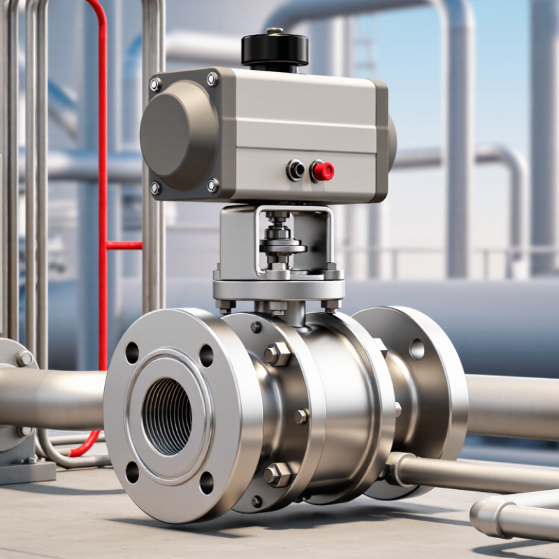
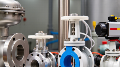
A pneumatic ball valve uses compressed air to turn a ball with a central bore. The actuator usually rotates it 90 degrees: the bore aligns with the pipe to allow flow, then turns across it to stop flow. A rack-and-pinion actuator converts piston travel into rotation. A solenoid valve directs air to one side of the piston; in spring-return designs, a spring moves the valve to its designated position when air is lost. Check that position against the process requirements. It is not always “closed.”
Look closely at the actuator during selection. A small air port, tubing, and solenoid sit above the valve body; leaks or low supply pressure can prevent full travel. The U.S. Department of Energy’s Improving Compressed Air System Performance: A Sourcebook for Industry reports that compressed-air systems use about 10% of electricity in U.S. manufacturing, and leaks may waste 20–30% of compressor output. Those figures make air consumption and leak checks practical selection concerns, not minor details.
For reliable operation, compare actuator torque with the valve’s breakaway torque at the actual pressure and temperature. Confirm the air supply, duty cycle, and required failure position, then test travel and feedback signals during commissioning. A quarter-turn may look simple. Yet deposits, worn seals, or an undersized actuator can cause slow or incomplete closure. I would not assume the catalog torque covers every real condition; leave an appropriate margin and verify it with operating data.
Define the Operating Conditions and System Requirements
Before selecting a pneumatic ball valve, map the actual operating conditions—not just the nominal pipe size. Record the medium, normal and peak pressure, temperature range, flow rate, and pressure differential across the valve. Check the actuator’s available air pressure too; a low supply can leave it short of the torque needed to close under load. Small details matter. Note cycle frequency, required shutoff tightness, and whether the valve must fail open or closed when air or power is lost. Also check air quality and drainage, especially where moisture or particles could affect the actuator.
The U.S. Department of Energy’s Improving Compressed Air System Performance guide reports that
leaks can waste 20–30% of compressed air in a typical plant.
That figure describes the system, not a valve’s individual consumption, but it shows why actuator air use and leakage deserve attention. Compare the valve’s flow coefficient with the system’s demand, then confirm the body and seal materials suit the fluid and temperature. A datasheet can make sizing look exact. In practice, uncertain peak conditions or future process changes can undermine that confidence, so record assumptions and verify them with operating data where possible.
Select the Valve Type, Size, and Port Configuration
A pneumatic ball valve should match the job, not just the pipe. Start with the flow path. A two-way valve opens or blocks flow. A three-way valve can divert or mix it, but its port pattern must match the piping layout. Check the valve diagram before ordering; similar-looking configurations may route fluid differently. For simple on/off service, a two-position actuator is often suitable. Choose a control actuator only when the process needs intermediate positioning.
Size the valve for the required flow and pressure drop. Pipe diameter is a useful starting point, not a complete sizing method. A full-port bore reduces restriction and suits applications where flow capacity or solids passage matters. A reduced-port bore may be adequate for many general services. Confirm the medium, operating temperature, pressure, and expected cycle frequency. Then check that the actuator’s torque exceeds the valve’s requirement at the actual differential pressure. I would still verify this against the supplier’s sizing data; a comfortable-looking margin can disappear under demanding conditions.
Tips: Confirm whether the valve needs threaded, flanged, or other end connections, and check the available instrument-air pressure. Specify the required fail position, too. Small details matter: a tight installation space or an unexpected air-supply limit can change the best configuration. Recheck the port layout before installation.
Match the Valve Materials and Actuator to the Application
How to Choose a Pneumatic Ball Valve?
Match the Valve Materials and Actuator to the Application
Start with the fluid, temperature, pressure, and cleaning routine. Stainless steel can resist corrosion in many wet processes, while carbon steel may suit compatible, less corrosive services. Check the seat and seal materials too. A stainless body cannot prevent failure if an incompatible seal swells or hardens. For abrasive media, inspect the valve’s wear limits rather than relying on material names alone. Conditions vary.
Size the actuator for the valve’s breakaway torque at the actual operating pressure. Allowance may be needed for cold starts, deposits, or aging seals, but excessive oversizing can add cost and air use. Specify the required fail position and confirm that available air pressure can deliver it. The U.S. Department of Energy’s Improving Compressed Air System Performance: A Sourcebook for Industry reports that compressed air can account for about 10% of industrial electricity use, and up to 30% in some facilities. Efficient sizing matters. Still, a datasheet calculation should be checked against real operating conditions.
Tips: Verify fluid compatibility with the seal supplier. Check minimum air pressure, cycle frequency, and torque data. Then test the assembly under representative conditions; selection tables can miss awkward details.
Verify Compatibility, Safety Standards, and Maintenance Needs
A pneumatic ball valve should match the fluid, pressure, temperature, and pipe connection. Check the body and seat materials against the actual medium, including cleaning chemicals. A seal that works with water may swell or harden in oil. Confirm the pressure rating covers both normal operation and credible pressure spikes. Then compare actuator torque with the valve’s breakaway torque, especially under maximum pressure. Do not size from pipe diameter alone.
Compatibility matters.
Review the required safety standards for the equipment and installation, and ask for current test reports or material documentation. Verify that the actuator’s fail position suits the process: some systems need the valve to close when air supply is lost, while others need it open. Check the available air pressure, connection details, and control signal before ordering. A checklist helps, though it can still miss an unusual operating condition; have a qualified engineer review uncertain cases.
Plan maintenance before installation. Leave enough clearance to inspect fittings, replace seals, and remove the actuator without dismantling nearby pipework. Ask how often the valve should be cycled or inspected under your service conditions. Dust, moisture, and frequent switching can change maintenance needs. Keep spare seals only when their material and size are confirmed, and record leaks, slow movement, or rising air consumption during routine checks. Those small signs are easy to overlook.
Related Posts
-
How to Optimize Your Pipeline Efficiency with Ball Check Valves: Best Practices and Insights
-
2026 Top Relief Valve Trends for Global Buyers Insights?
-
Understanding the Role of Check Valves in Fluid Control Systems for Enhanced Efficiency
-
How to Choose the Right Industrial Valves for Your Manufacturing Needs
-

2025 Top 10 Air Valve Innovations You Must Know About
-
2026 Best Diaphragm Valve Types for Global Buyers?
