
How to Choose a Pneumatic Control Valve?
Choosing a pneumatic control valve is not just a matter of matching pipe size. The right choice depends on flow rate, pressure drop, fluid properties, temperature, and the required control accuracy. A valve handling clean air may behave differently from one exposed to moisture, oil, or corrosive process media. Small details matter.
The U.S. Department of Energy’s Improving Compressed Air System Performance sourcebook highlights the energy burden of compressed air. It notes that compressed air can represent about 10% of industrial electricity use. This figure describes entire systems, not the savings from one valve. Still, it shows why leakage, pressure loss, and poor control deserve attention. An oversized valve can make stable control harder, while an undersized valve may restrict flow when demand rises. Catalog tables help, but they cannot replace real operating data.
A sound selection process starts with the valve’s duty and expected operating range. This guide will explain how to assess flow capacity, pressure and temperature limits, body and seal materials, and actuator requirements. It will also cover fail-open or fail-closed behavior, control signals, and positioners. For sizing, IEC 60534 provides recognized methods for control-valve calculations. There is no perfectly clean shortcut: uncertain process data can still lead to a poor fit. Careful checks before purchase can reduce that risk and support reliable, responsive operation.
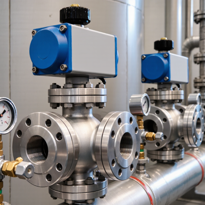
Define Service Conditions: Flow, Pressure Drop, Temperature, and Fluid Phase
Before selecting a pneumatic control valve, record minimum, normal, and peak flow—not just the design value. Note inlet and outlet pressures at the valve, then calculate the actual pressure drop. IEC 60534-2-1 provides sizing equations for control valves handling compressible and incompressible fluids. For gases, include absolute pressure, temperature, and compressibility; high pressure drops can lead to choked flow. Small details matter. A flow estimate based on one operating point may miss startup surges or turndown.
Temperature and fluid phase can change the selection. NIST’s Chemistry WebBook lists water’s saturation pressure at 100°C as about 101.3 kPa absolute. If local pressure approaches a liquid’s vapor pressure, flashing or cavitation may occur. For steam or gas, confirm whether the fluid remains single-phase across the valve. Check the phase. A temperature reading alone does not establish it; pressure matters too.
Use measured operating data where possible, including fluid composition and expected pressure fluctuations. For a real installation, compare normal conditions with the worst credible combination of flow and pressure. A first-pass calculation can still be wrong if the downstream pressure was taken far from the valve. That oversight is easy to make. Recheck the assumptions against the process data and the applicable IEC sizing method before specifying the valve.
Size the Valve Using IEC 60534 / ISA-75 Cv Methods and Required Rangeability
Size the valve at real operating conditions, not from pipe diameter alone. IEC 60534-2-1 and ISA-75.01.01 define flow-coefficient sizing methods that account for pressure drop and fluid properties. For a simple, non-choked water case, 100 US gallons per minute across a 25 psi pressure drop requires about Cv 20, using Cv = Q√(SG/ΔP). That is a calculated example, not a final valve selection. Gas, flashing liquid, and choking require additional correction factors. Small details matter. Include minimum, normal, and peak flow, plus upstream pressure and temperature. A clean spreadsheet can still miss commissioning conditions.
Set rangeability from the actual flow window: maximum required flow divided by minimum controllable flow. If the process needs 40:1, a valve’s published inherent rangeability should exceed that figure, with margin. Installed rangeability can be lower because the piping system changes pressure drop as flow rises. Not just catalog Cv. Check the valve characteristic, actuator resolution, and expected operating pressure at both ends of the range. IEC 60534-2-1 and ISA-75.01.01 provide the sizing framework; neither guarantees one universal rangeability for every valve design. Ask for documented test data under stated conditions. Then review the assumptions with operations staff. I would revisit the calculation after startup, too. Real process behavior is rarely as tidy as the model.
Select Body and Trim Materials for Pressure Class, Corrosion, and Cavitation
When choosing a pneumatic control valve, match the body material to both the pressure class and operating temperature. A class rating is not a universal pressure limit; allowable pressure changes with temperature and material. Check the valve’s pressure-temperature data against maximum operating and upset conditions. Leave room for real process variation. A carbon-steel body may suit a clean, compatible service, while stainless steel or an alloy may be needed for corrosive fluids. Small details matter.
The trim contacts the process directly, so check its chemical compatibility, wear resistance, and temperature limits. Compare the fluid composition with the body, plug, seat, and stem materials, including during cleaning or startup. A corrosion-resistant body does not guarantee a corrosion-resistant trim. It is tempting to choose stainless steel as a blanket solution, but chloride levels, acids, and temperature can change the result. That shortcut can fail.
Cavitation deserves special attention when the valve throttles liquid. A large pressure drop can form vapor bubbles that collapse downstream, damaging trim and producing noise or vibration. Pneumatic describes the actuator, not the fluid behavior; cavitation can still occur in a pneumatic control valve. Review upstream and downstream pressures, liquid temperature, and vapor pressure. Ask for sizing that identifies cavitation risk, then consider hardened trim or a suitable pressure-reduction design. Verify material certificates and pressure ratings against the actual service data, not just a nominal line size.
Choose Actuator and Fail-Safe Action; Check the 3–15 psi (20–100 kPa) Signal
How to Choose a Pneumatic Control Valve?
Choose the actuator and failure position before comparing valve bodies. Decide whether the process should move toward open or closed when instrument air disappears; neither action is universally safer. A spring-return actuator can drive the valve to its selected position, while a double-acting actuator may need additional accessories to define its response. Size the actuator for the worst expected pressure drop, not just normal operation. ISA/IEC 60534-2-1 provides a recognized framework for control-valve sizing. Still, sizing calculations depend on accurate process data, which can be incomplete in early design.
Check the controller signal at the valve. The conventional range is 3–15 psi(g), approximately 20–100 kPa(g); more precisely, 3–15 psi is about 21–103 kPa. Confirm that the positioner accepts the specified range and that its calibration matches the controller output. A mismatch can leave the valve partly open even when the display looks normal. Verify response at the low, midpoint, and high signal pressures, then test the air-failure action separately. In practice, this check is easy to rush.
Tips: Confirm minimum air supply, actuator thrust, and actual fail position during commissioning. Record the measured pressures. A small mismatch matters. Revisit the choice if the process hazard review changes.
How to Choose a Pneumatic Control Valve: Actuator Signal Range
The common 3–15 psi pneumatic signal range converts to approximately 20.7–103.4 kPa, often rounded to 20–100 kPa. Confirm that the actuator accepts the controller’s signal range. Select the fail-safe action separately according to the actuator configuration and the process requirements.
Verify Instrument Air Supply: Typically 0.4–0.7 MPa, with ISO 8573-1 Quality Checks
How to Choose a Pneumatic Control Valve?
Before choosing a pneumatic control valve, check that the instrument air supply matches the actuator’s requirements. A typical operating range is 0.4–0.7 MPa, but the valve’s technical specifications take priority. Measure pressure near the actuator while the valve is moving, not only at the compressor header. A long, narrow tube or partly blocked filter can reduce pressure under load. Check under motion. Small detail. Still important.
Air quality matters as much as pressure. ISO 8573-1:2010 classifies compressed air by particles, water, and total oil; it does not set one universal class for every valve. As reference points, water Class 4 allows a pressure dew point of up to +3°C, and total-oil Class 2 limits oil to 0.1 mg/m³. Specify the required classes for the operating environment, then verify them with suitable air-quality tests. A clean-looking line can still carry moisture. I would not assume a filter alone proves the air meets the target.
Related Posts
-
How to Choose a Pneumatic Control Valve in 2026?
-
10 Best Flow Control Valves for Industrial Applications
-

What is a Pressure Valve and How Does it Work?
-
Common Issues Faced by Global Buyers When Sourcing Gas Valves: A Comprehensive Guide
-

Ultimate Guide to Selecting the Right Industrial Valves for Your Applications
-
2026 Top Relief Valve Trends for Global Buyers Insights?